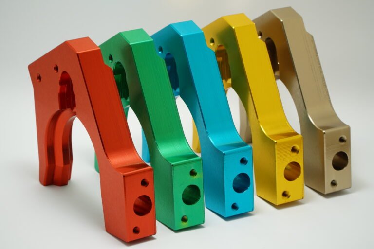
Even tiny errors in tolerance can cause huge failures—fit issues, vibration, and expensive rework all begin with poor control in the machining process.
To achieve low tolerance control in precision machining, you need advanced equipment, skilled programming, strict process control, and real-time inspection methods.
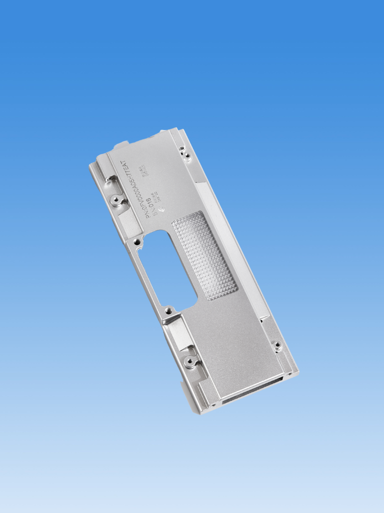
I’ve worked with customers who rejected entire batches for being off by just 5 microns. In industries like medical and aerospace, the margin for error is almost zero. Getting low tolerances right is not just about machine specs—it’s about everything from raw materials to operator habits.
What is the tolerance for precision machining?
Every buyer wants “tight tolerances,” but many don’t know what that really means—or how tight is too tight.
Precision machining typically requires tolerances between ±0.005 mm to ±0.01 mm, depending on the part’s function and industry requirements.

In general-purpose machining, ±0.1 mm is common. But in precision work, that becomes unacceptable. For example, in Swiss-type CNC machining, especially for medical and electronic parts, we often work within ±0.005 mm. That’s about the thickness of a human hair. But keep in mind: tighter tolerance increases cost, machine time, and scrap risk.
Here’s a simple tolerance reference:
| Tolerance Range | Classification | Example Applications |
|---|---|---|
| ±0.1 mm | General machining | Brackets, covers |
| ±0.01 mm | Precision machining | Shafts, bushings, gears |
| ±0.005 mm or less | Ultra-precision | Aerospace, medical, optics |
One client once requested ±0.002 mm for a connector pin. We had to use temperature-controlled rooms, diamond tooling, and inspect every piece with a high-end CMM. It cost 3x more, but it worked perfectly.
How to determine machining tolerances?
Without the right tolerance from the start, parts end up too loose, too tight—or worse, completely unusable.
To determine machining tolerances, consider function, material, assembly fit, and the customer’s application; balance between performance and manufacturing cost.
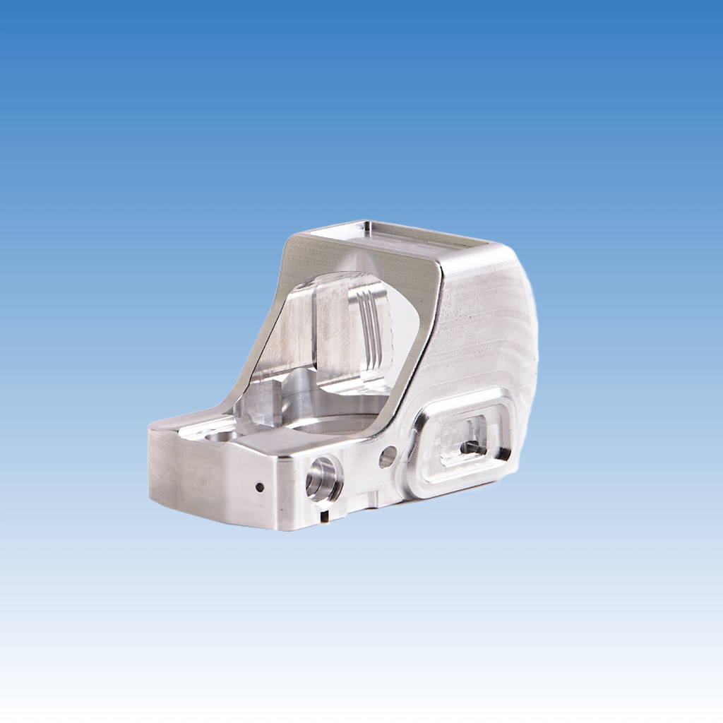
You can’t choose a tolerance in isolation. Every part has a purpose. If it’s a sliding shaft, you need clearance. If it’s a press-fit, you need interference. We work with our customers to define tolerances that match their real-world use. If they just copy old drawings with unrealistic tolerances, it creates waste and extra cost.
Here’s how we guide our clients:
- Ask about function – Does the part rotate, slide, press-fit, or seal?
- Material matters – Aluminum expands more than steel. Softer metals distort more under cutting forces.
- Machining process limits – Don’t ask ±0.002 mm from a rough milling machine.
- Inspection capability – Only assign tolerances we can measure reliably.
| Factor | Impact on Tolerance |
|---|---|
| Part function | Determines tightness needed |
| Material | Affects deformation |
| Machining method | Limits achievable tolerance |
| Assembly type | Sets clearance/interference |
We often recommend GD&T (Geometric Dimensioning & Tolerancing) to define critical features precisely without over-tolerancing non-essential areas.
What is the ISO standard for machining tolerances?
Some buyers ask for ISO fit classes but don’t explain the tolerance values they expect. That creates confusion and risk.
ISO 2768 and ISO 286 define general tolerances and fit classes for machining. These help standardize expectations and simplify technical drawings.
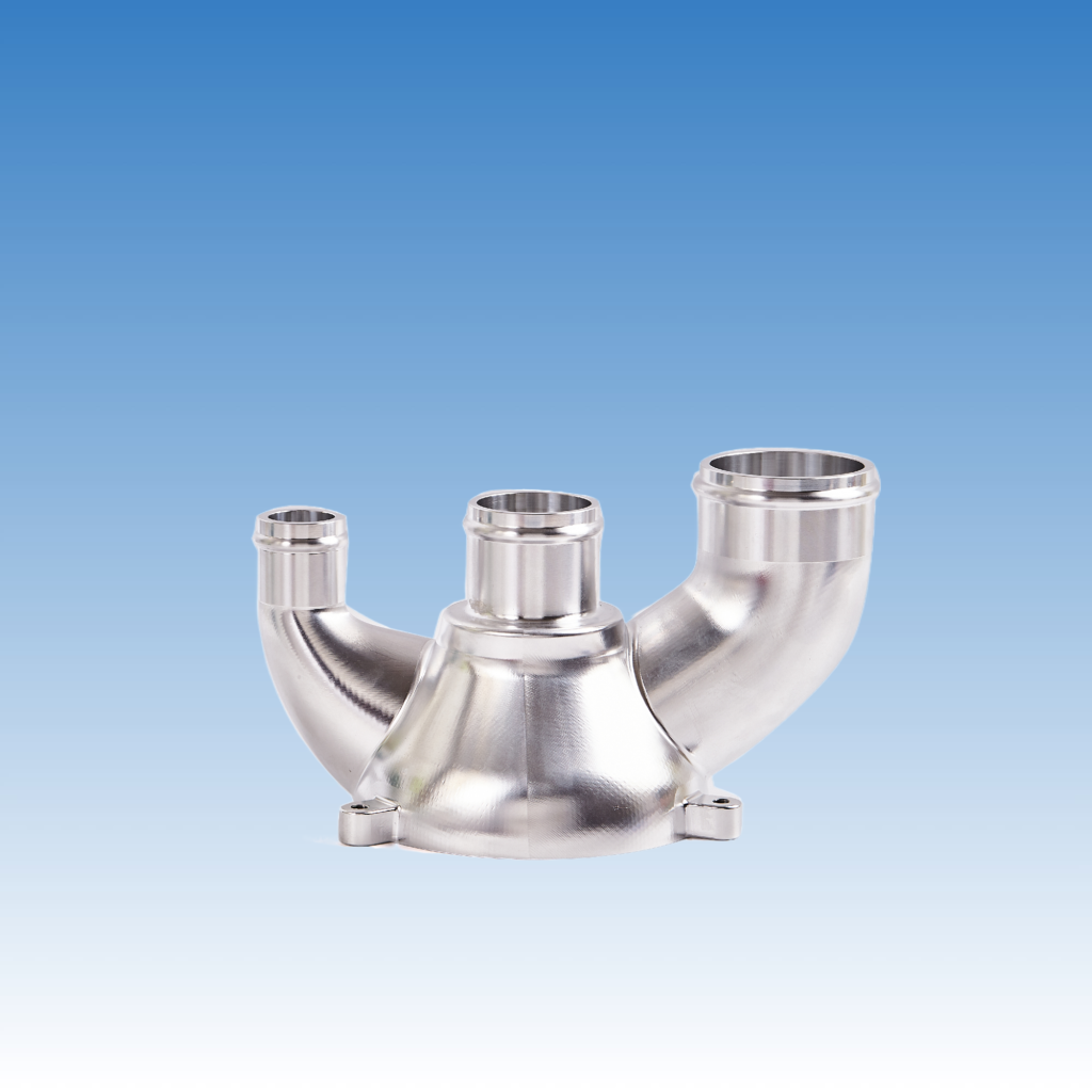
ISO 2768 is the most used standard for non-critical dimensions. It gives general tolerances based on length range and part type. ISO 286 defines limits and fits, like H7/g6, often used for shafts and holes. This system helps avoid misunderstanding and saves time on quoting and production.
We always recommend clients include ISO tolerance references in their drawings. For example, “ISO 2768-mK” tells us to apply medium tolerance on metal machined parts. That way, we avoid back-and-forth emails.
Here’s a simplified breakdown:
| Standard | Scope | Example Use |
|---|---|---|
| ISO 2768 | General tolerances | Non-critical dimensions |
| ISO 286 | Hole & shaft fits | Bearings, shafts |
| ISO 1101 | Geometric tolerancing | Flatness, roundness, etc. |
Using these standards helps us align with international buyers, especially from Germany or the UK, where precision norms are strict.
Is lower tolerance better?
Lower is not always better. Many buyers confuse tight tolerance with better quality—until they get the invoice.
Lower tolerance is not always better; it must match the part’s function, otherwise it increases cost, complexity, and rejection rates unnecessarily.
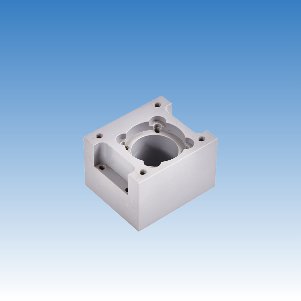
Over-tolerancing is one of the biggest cost drivers in machining. A drawing with ±0.005 mm on every feature makes production slow, raises tool wear, and drives inspection costs up. Worse, it raises the chance of rejection even if the part works fine.
I once had a customer insist on ±0.005 mm across the board, including on cosmetic holes. We had to quote 40% higher than necessary. After some discussion, we relaxed the non-critical features and saved him thousands—without affecting performance.
Here's a trade-off table:
| Tolerance Level | Cost Impact | Use Case | Risk if Misused |
|---|---|---|---|
| Loose (±0.1 mm) | Low | Covers, brackets | Loose fit, rattle |
| Medium (±0.01 mm) | Moderate | Housings, threads | Balanced, stable |
| Tight (±0.005 mm) | High | Bearings, gears | Costly if unnecessary |
Always ask: what is the part really doing? That guides the right tolerance level. Buyers who focus on function get better pricing and faster delivery.
Conclusion
Achieving low tolerance control in precision machining requires the right balance of engineering knowledge, machining capability, and clear communication with the buyer.

